Deploy Highly-Available Three-Tier Architecture to AWS using Terraform

INTRODUCTION.. When developing a cloud-based application, it’s essential to focus on the architecture and environment to ensure it is scalable, available, and secure. Infrastructure-as-Code (IaC) tools like Terraform have gained popularity for automating the deployment and management of cloud infrastructure.
This article will guide you through deploying a highly available three-tier architecture in AWS using Terraform. The architecture includes an EC2 Auto Scaling group for both the web (frontend) and application (backend) tiers, an RDS MySQL database for the data tier, and a bastion host for secure remote access.
Terraform allows us to efficiently deploy and manage resources while ensuring the architecture remains scalable, highly available, and secure. Let’s explore the steps to deploy this robust three-tier architecture in AWS using Terraform.
What is Three-Tier Architecture and Why Use It?
Three-Tier Architecture is a widely adopted architectural pattern that enhances scalability, availability, and security for cloud-based applications. This architecture divides an application into three separate layers, each with distinct functions that operate independently. By distributing the application across multiple Availability Zones and segmenting it into these three layers, the architecture achieves high availability and resilience.
If an Availability Zone fails, the application can automatically scale resources to another zone without impacting the rest of the application. Each tier is protected by its own security group, allowing only necessary traffic for its specific tasks. This setup effectively addresses various challenges faced by cloud applications.
What is Three-Tier Architecture and Why Use It?
Once we have the proper licensing we need to route applications to Microsoft Defender for Cloud Apps. In the Azure Portal, go to Conditional Access and create a new Policy.
Three-Tier Architecture consists of three layers:
1. Web/Presentation Tier (Front End): Contains the user-facing elements such as web servers and interfaces.
2. Logic Tier (Back End): Contains the backend components and application logic needed for data processing and functions.
3. Data Tier (Database): Manages the application’s data, typically where databases are stored.
Prerequisites:
An AWS account with IAM user access.
Reference: Terraform Registry
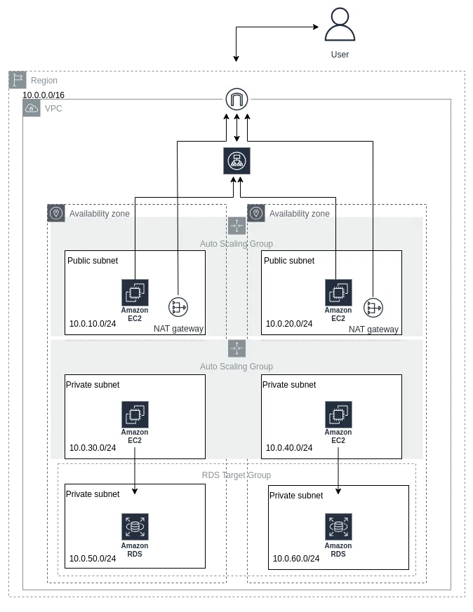
Architecture Diagram::

Components of the Three-Tier Architecture:
1. VPC Deployment: A VPC with a CIDR block of 10.0.0.0/16.
2. Public Subnets: Two public subnets with CIDR blocks 10.0.10.0/24 and 10.0.20.0/24, each in a separate Availability Zone to ensure high availability.
3. Private Subnets: Four private subnets with CIDR blocks 10.0.20.0/24 and 10.0.30.0/24 for the logic/application tier, and 10.0.40.0/24 and 10.0.50.0/24 for the database tier, all spread across different Availability Zones.
4. Database: An RDS MySQL instance.
5. Load Balancers: One application load balancer for directing traffic to the public subnets and another for routing traffic from the web tier to the application tier.
6. EC2 Auto Scaling Groups: One in each public subnet (for the web tier) and one in each private subnet (for the logic/application tier) to maintain high availability.
7. Networking Components: An Internet Gateway, NAT Gateway, and Elastic IPs for the EC2 instances.
8. Bastion Host: A bastion host for secure access to the application servers.
Terraform provider configs:
The main.tf file in current directory structure is a configuration file that defines the cloud provider and the other required plugins that Terraform will use to manage resources within that provider.
Network Architecure:
The network architecutre of the current implementation contains four subnets two public and two private. Single Internet and NAT Gateway for public and private subnets.
The three-tier-vpc.tf, three-tier-gws.tf, and three-tier-rts.tf files in Terraform configurations are crucial for deploying a scalable and highly available AWS infrastructure. These files define the network components, including a VPC, two public subnets, four private subnets, an Internet Gateway (IGW), a NAT Gateway, an Application Load Balancer (ALB), and route tables. The VPC provides an isolated environment, public subnets host publicly accessible resources, and private subnets host restricted-access resources. The IGW manages public traffic, the NAT Gateway enables internet access for private subnets, and the ALB distributes traffic for optimal performance. Terraform ensures efficient management and scalability of this network infrastructure.
VPC & Subnets creation:
Internet Gateway creation:
Route Tables Creation:
To enable communication between the web and application tiers, we need two route tables: one public for the web tier and one private for the application tier. The public route table links to the public subnet with the load balancer, while the private route table connects to the private subnets with the application servers. Associating these route tables with the respective subnets ensures controlled traffic flow and proper communication between the web and app servers.
NAT Gateway creation:
A NAT gateway allows private subnet instances to access external resources and the internet for essential services. For high availability, it’s best to deploy two NAT gateways in separate public subnets (one per Availability Zone). However, we’ll deploy just one for now.
Web Tier Creation:
The Web Tier, or ‘Presentation’ tier, is where the user interface of our application is hosted. For Brainiac, this involves launching web servers for the front end.
Components to build:
1. A launch template defining EC2 instance details.
2. An Auto Scaling Group (ASG) for dynamic instance provisioning.
3. An Application Load Balancer (ALB) to route incoming traffic.
4. A security group to manage traffic to web servers.
The ASG ensures high availability by dynamically adjusting the number of instances based on demand. The launch template specifies instance details like size, AMI, and security settings. The ALB distributes traffic evenly and maintains high availability by monitoring server health. The security group restricts access to necessary ports and sources, enhancing security.
ASG & Launch template creation:
To avoid single points of failure and ensure high availability, we’ll create an Auto Scaling Group (ASG) that dynamically provisions EC2 instances across multiple Availability Zones in our public subnets. A template will be used by the ASG to launch these instances as needed.
LoadBalancer Creation:
We need an ALB to distribute incoming HTTP traffic to the correct EC2 instances. The ALB will listen on port 80 and route traffic through a target group. The ASG will have a desired capacity of 2 instances, with a minimum of 2 and a maximum of 3 instances.
Logic-Tier Creation:
The Logic Tier is where the core functionality of our app resides, handling tasks like processing requests and data storage. To ensure reliability and scalability, we will implement components similar to the Web Tier, plus a few additional ones:
1. Launch Template: Defines the type of EC2 instances for our application, allowing quick and consistent provisioning.
2. Auto Scaling Group (ASG): Automatically adjusts the number of EC2 instances based on traffic, ensuring high availability and scalability.
3. Application Load Balancer (ALB): Routes traffic from the Web Tier to the Application Tier, balancing the load and ensuring availability.
4. Bastion Host: Provides a secure way to connect to application servers without exposing them to the public internet.
ASG & Launch Template Creation:
To ensure high availability and avoid single points of failure, we’ll set up an Auto Scaling Group (ASG) to dynamically manage EC2 instances across multiple AZs in public subnets. We’ll use a template for the ASG to launch instances in private subnets, where the application source code resides. For security, we’ll restrict access from outside, allowing only ICMP–IPv4 from the web tier security group to ping the application server from the web server.
Data-Tier Creation:
The Data Tier will store critical data like user info and transactions. Application servers will read/write to a MySQL-based RDS to provide content and services to the Web Tier and users.
We’ll create a database security group for MySQL traffic, a DB subnet group for correct subnet placement, and an RDS MySQL database. These components will secure and connect our Database Tier to the other application tiers. Next, we’ll define these in the three-tier-rds.tf file.
Let’s deploy!
Ensure your AWS credentials are set and you’re in the root directory.
1. terraform init
Initialize the configuration and downloads provider plugins.
2. terraform plan
Create an execution plan, showing what resources will be created, modified, or deleted.
3. terraform apply
Apply the configuration to create or modify resources.
Don’t forget to delete your resources (ASG, ALB, DB, NAT Gateway) and release all elastic IPs to avoid charges.
4. terraform destroy
Destroy the resources created in the earlier steps.
Contact
Etecnest as your trusted IT and Cloud Service Provider. We are dedicated to delivering innovative solutions that propel your business into the digital future. Whether you are seeking robust IT services, comprehensive cloud solutions, or a tailored combination of both, we are here to meet your unique needs.
Our Address
J P Nagar 509 Area Pune 411032
Email Us
info@etecnest.com
Call Us
+91 7875092767
